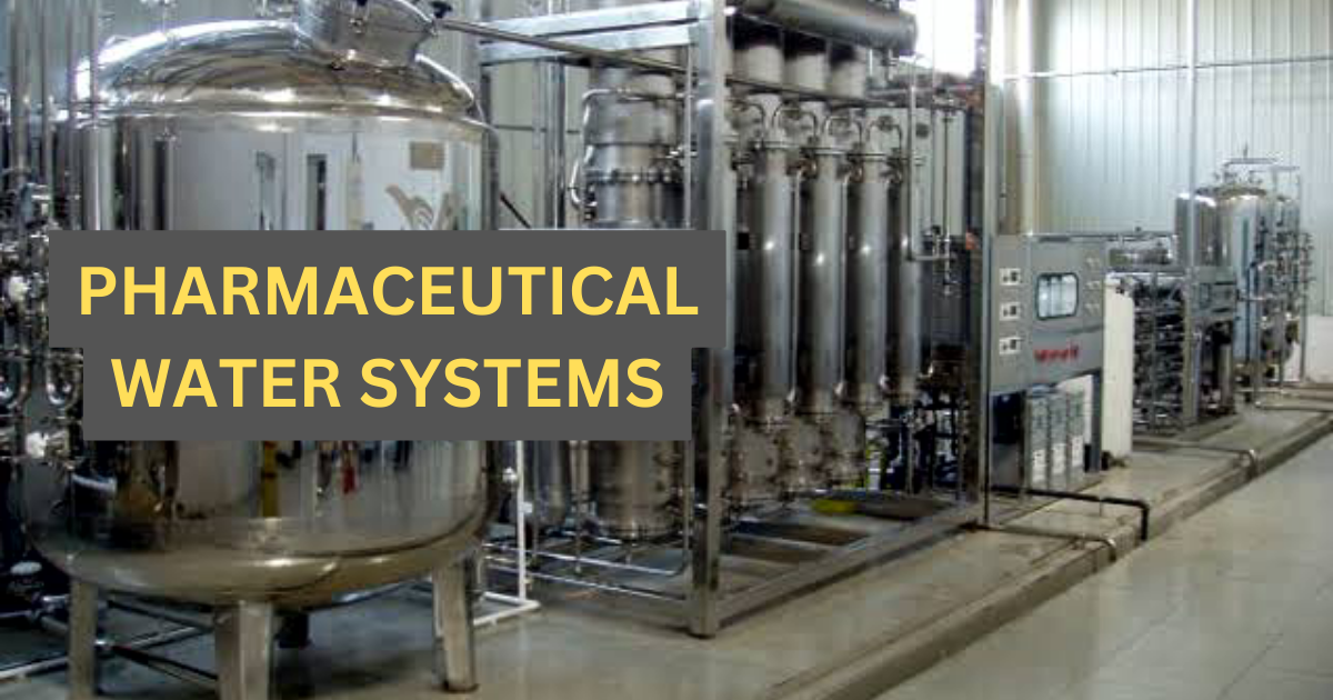
Pharmaceutical water systems are critical components in pharmaceutical manufacturing facilities that provide water of high quality and purity for various purposes, including drug formulation, cleaning, and sterilization processes. The water used in pharmaceutical manufacturing must meet stringent standards to ensure the safety and efficacy of pharmaceutical products.
Pharmaceutical water systems are designed to produce water with controlled levels of impurities, such as microorganisms, particles, dissolved solids, and organic compounds. These impurities can have a detrimental effect on product quality, stability, and patient safety if present in the pharmaceutical water. There are several types of water used in pharmaceutical manufacturing, each with its own quality requirements and applications.
The primary types of water used in pharmaceuticals include:
Purified Water (PW): Purified water is used for non-sterile pharmaceutical processes, such as solution preparation, cleaning, and rinsing. It meets the specifications outlined in the relevant pharmacopoeias, including limits on microbial counts, endotoxins, and chemical impurities.
Water for Injection (WFI): Water for Injection is used as a solvent in the preparation of parenteral (injectable) drugs. It must meet even higher quality standards than purified water, with lower microbial counts and endotoxin levels. WFI is typically produced by distillation or reverse osmosis.
Highly Purified Water (HPW): Highly Purified Water is used in critical pharmaceutical processes, such as the formulation of sensitive drug substances or final rinse steps in equipment cleaning. It undergoes additional purification steps beyond those used for purified water.
Pharmaceutical water systems typically consist of multiple stages or unit operations, including pre-treatment, primary purification, and distribution/storage. Pre-treatment steps may involve processes like filtration, sedimentation, and activated carbon adsorption to remove particulate matter, chlorine, and organic impurities. Primary purification methods commonly used include reverse osmosis, distillation, or a combination of both.
The design, installation, validation, and routine monitoring of pharmaceutical water systems are essential to ensure the production of water that consistently meets the required quality standards. Regulatory agencies, such as the United States Pharmacopeia (USP) and the European Pharmacopoeia (EP), provide guidelines and specifications for pharmaceutical water systems, which manufacturers must comply with to ensure compliance with Good Manufacturing Practices (GMP) and product quality assurance.
Regular monitoring, maintenance, and periodic validation of pharmaceutical water systems are necessary to prevent contamination, maintain system performance, and ensure the production of high-quality water throughout the manufacturing process.
Design Basis of Pharmaceutical Water Systems
Designing a pharmaceutical water system requires careful consideration of various factors to ensure that the system meets the specific quality and regulatory requirements.
Feed Water Quality:
A raw water analysis report plays a crucial role in the design of a pharmaceutical water system. It provides essential information about the quality and composition of the raw water source, which is used as the feed for the water system. A raw water analysis report helping in the selection of treatment processes, sizing of equipment, validation of the system, compliance with regulatory standards, and ongoing maintenance and monitoring. It ensures the production of water that meets the necessary purity and quality requirements for pharmaceutical manufacturing processes.
The incoming or raw water coming at inlet of system has following characteristics. Following parameters of raw water (System feed Water) need to analyzed before going forward to design of water system
| Parameter | Unit | Specification | WHO Guidelines |
| pH | – | 6.5-8.5 | |
| Color (Filtered) | Pt Co. Unit | – | 15 |
| Turbidity | NTU | – | 5 |
| Total Hardness as CaCO3 | ppm | 150 | – |
| Iron, Fe | ppm | 0.3-1.0 | 0.3 |
| Manganese, Mn | ppm | – | 0.4 |
| Arsenic, As | μg/L | – | 10 |
| Chloride, Cl | ppm | – | 250 |
| Fluoride, F | ppm | – | 1.5 |
| Nitrate-Nitrogen, NO3-N | ppm | – | 50 |
| Total Dissolved Solids (TDS) | mg/L | 1000 | 1000 |
| Total Suspended Solids | ppm | < 200 | Not available |
| Residual Chlorine | ppm | 0.2-1.0 | Not available |
Following parameters were also need to analyses
| Silt Density Index (SDI) | – |
| Total Organic Carbon (TOC) | ppb |
| Colloidal Silica as SiO2 | ppm |
| Reactive Silica asSiO2 | ppm |
| Pathogens | – |
Also read: Feed water characterisation for water system
Product Water Quality
The product water outlet quality plays a vital role in the design of a pharmaceutical water system. It ensures compliance with regulatory standards, guarantees the quality and safety of pharmaceutical products, maintains process reliability and consistency, facilitates validation and qualification, and supports documentation and auditing requirements. Designing a robust water system that consistently produces high-quality product water is crucial for pharmaceutical manufacturing processes.
Following are the primary types of product water qualities used in pharmaceuticals:
| Purified Water Quality at all POU Valves for PW Generation System | ||||
| Sr.No. | Parameters | Unit | USP-XXXVI | Design |
| 01 | Conductivity at 25 0C | µs/cm | 1.3 | 1.3 |
| 02 | pH | – | 5 – 7 | 5 – 7 |
| 03 | TOC | ppb | 500 | 500 |
| 04 | Microbial Count | Cfu/ml | 100 | 100 |
| 05 | Pathogens | – | Absent | Absent |
| Purified Water Quality at all POU Valves for PW Storage & Distribution System | ||||
| Sr.No. | Parameters | Unit | USP-XXXVI | Design |
| 01 | Conductivity at 25 0C | µs/cm | 1.3 | 1.3 |
| 02 | pH | – | 5 – 7 | 5 – 7 |
| 03 | TOC | ppb | 500 | 500 |
| 04 | Microbial Count | Cfu/ml | 100 | 100 |
| 05 | Pathogens | – | Absent | Absent |
| Purified Water Quality at all POU Valves for WFI Generation System | ||||
| Sr.No. | Parameters | Unit | USP-XXXVI | Design |
| 01 | Conductivity at 25 0C | µs/cm | 1.3 | 1.3 |
| 02 | TOC | ppb | 500 | 500 |
| 03 | Microbial Count | cfu/100ml | 10 | 10 |
| 04 | Pathogens | – | Absent | Absent |
| 05 | Endotoxin | EU/ml | 0.25 | 0.25 |
| Purified Water Quality at all POU Valves for WFI Storage & Distribution System | ||||
| Sr.No. | Parameters | Unit | USP-XXXVI | Design |
| 01 | Conductivity at 25 0C | µs/cm | 1.3 | 1.3 |
| 02 | TOC | ppb | 500 | 500 |
| 03 | Microbial Count | cfu/100ml | 10 | 10 |
| 04 | Pathogens | – | Absent | Absent |
| 05 | Endotoxin | EU/ml | 0.25 | 0.25 |
Design of Pharmaceutical Water System
The pharmaceutical water system is designed in the following sections
- Pre-treatment System
- Purified Water Generation
- Purified Water Storage & Distribution System
- WFI & Pure Steam Generation System
- WFI Storage & Distribution System
Pre-Treatment System
The purpose of Pre-treatment is to supply potable water to the Purified Water Generation System. The pre-treatment system consists of the following units
- Chlorination of Raw Water
- Multi Grade Filter
- Micron filters
- Duplex Softener
- Ultrafiltration System
- Reverse Osmosis System
Chlorination of Raw Water
NaOCl re-circulation loop is provided at the Raw Water Storage Tank to ensure minimum level of NaOCl in the tank. Raw water is chlorinated using sodium hypochlorite (NaOCl). Purpose of chlorine re-circulation is to avoid bacterial growth in the feed water.
NaOCl dosing unit consist of NaOCl dosing pump and NaOCl solution tank. A recommended ppm is dosed at recirculation line of raw water tank. Chlorine dosing pump will maintain the dosing speed based on the chlorine sensor value
Multi Grade Filter
It consists of multi–grade sand particles which are layered intimately in specific proportions. This ensures one obtains both surface and depth filtration. The sand filter helps to achieve a reduction of suspended solids. This in turn helps to prevent physical fouling due to major particulate matter of downstream units.
Micron filters
Micron filters are typically made of materials such as polypropylene, nylon, or cellulose, and they can be pleated or non-pleated depending on the application. They are available in a range of micron sizes, from 0.1 microns to 100 microns or more, allowing for the removal of various types and sizes of particles.
Duplex Softener in Series
Chlorinated water will pass through a Duplex Softener with the help of a Feed Pump, where the total hardness of water is removed by using Ion exchange resin. The purpose of softening system is to avoid scaling of RO membranes due to the presence of calcium and magnesium ions.
The water softener operates on principle of Ion exchange and softens the filtered water from Bag Filter. Calcium and Magnesium are replaced by sodium. Salt content (TDS) of water remains unchanged. The two softeners are connected in series. Softener-1 always acts as working and softener-2 is always act as safety. The working softener is controlled based on the volume of water processed. Regeneration of the softener is initiated after a preset volume of water has been processed, i.e. after a preset amount of water passes from the water meter. When the preset amount of water passes from the water meter, regeneration is initiated automatically. During regeneration of softener 1, softener 2 will acts as working and vice versa. Once regeneration has been completed, the working softener is connected back into the circuit.
The softener-2 is regenerated after three regeneration cycles of the softener 1. This is also settable on the HMI. The softener-1 and softener-2 can never be regenerated simultaneously. The incoming water is softened as it flows through the softener at normal line pressure. When ion- exchanger resins become saturated with hardness agents, they have to be regenerated with the aid of sodium chloride (common salt) which is supplied in the form of brine (salt solution). The brine is mixed in the brine tanks.
Ultrafiltration System
The Ultra Filtration unit is installed to remove SDI causing particles in the process. It will also remove Bacteria, viruses, colloidal silica, fine sand etc. The filtered water coming from DSF passes through cartridge filter and then to Ultrafiltration membrane. The UF membrane is hollow fibre type made of polyether Sulfone material. The Ultra filtered water will be stored in a UF Product tank. UF Product tank is equipped with all accessories like level Switch, drain valve and vent pipe. After UF product tank ultra-filtered water will pass to RO system.
The Ultra filtration unit includes Hollow Fibre 100 KD Membranes, Cartridge filter , UF Backwash pump ,UF Product Tank & piping on a skid mounted system. High- pressure switch is provided at the feed & backwash inlet of the UF membranes to protect UF membranes from high working pressure as the maximum operating pressure for membrane is 4 bar.
The Ultra Filtration system will perform an automatic backwash after every settable time of operation cycle or if differential pressure exceeds more than 1 bar. Backwash frequency of UF is settable on HMI and subject to change based on incoming load of suspended solids at UF.
The system can be chemically sanitized with NaOCl with the help of dosing pump. Sanitization is an automatic operation and to be performed normally after 20 backwash cycles.
NaOCl solution of 20 – 30 ppm concentration in dosing tank is fed by the dosing pump and UF backwash pump in the system for a preset period at atmospheric temperature. After this the solution is discarded and system is flushed with UF permeate & fresh feed water. After completion of sanitization, UF automatically switch over to Normal Mode from sanitization mode.
Reverse Osmosis System (Chemical Sanitisable)
The pretreated softened filter water after conditioning with help of dosing chemicals passes to the RO membranes via high-pressure pump. The chemical Sanitisable RO system consists of a bank of membranes, a high-pressure pump and all necessary instruments to monitor conductivity, pressure, etc. Purpose of primary RO is to reduce high content of dissolved ions, organic matters and microbial growth from incoming raw water before water passes to the main purified water generation system. RO product water will be stored in RO product tank and termed as Potable water.
Dosing system for conditioning of RO feed water
Antiscalant Dosing Unit:
Antiscalent dosing unit consist of Antiscalent dosing pump and Antiscalent solution tank. A recommended Antiscalent with known ppm is dosed at inlet of RO to avoid scaling of membranes due to silica content of water. Dosing pump frequency will be set based on inlet water flow to dose desired ppm level.
SMBS Dosing Unit:
SMBS dosing unit consist of SMBS dosing pump, SMBS solution tank and an ORP sensor. Before water enters in to RO membranes it is very important that all oxidizing agents from water must be remove. SMBS is reducing agent which removes chlorine which is left after softener.
Dosing pump frequency is controlled via PLC to maintain the inlet water ORP less than 400 mV. ORP Sensor is use to monitor inlet water chlorine after SMBS dosing. If ORP value goes above very high set point then water entry to RO membranes will stop and dumping valve will open till ORP gets normalized.
Plate Heat Exchanger & pH Dosing Unit:
RO treated water from RO Product Tank will be pumped to purified water generation system through plate heat exchanger to maintain the temperature 23 ± 2°C. Chilled water will be used to maintain the water temperature. Water from PHE will be dosed with NaOH to maintain basic pH.
NaOH Dosing Unit:
NaOH dosing unit consist of NaOH dosing pump, NaOH solution tank and a pH sensor. Dosing pump frequency is controlled via PLC to maintain the inlet water pH on alkaline side (i.e. between 8 to 8.5). Gaseous CO2 present in water converted to dissolve ionic form by NaOH dosing and easily removed by RO membranes.
Purified Water Generation System
The potable water from RO product tank will enter to the PW Generation system via plate type heat exchanger and will pass through the RO and EDI system to produce purified water Plate Type Heat Exchanger is provided to control the Temperature of Feed Water of PW generation system. It maintains the feed water temperature below 25 ºC with the help of Chilled Water on the other side of plates during normal service cycle.
PW generation system combines Reverse Osmosis with Electro-deionisation stages and it is Hot water sanitisable system.
Reverse Osmosis (RO)
Reverse osmosis is a membrane-based process which removes substances dissolved in the water and is used to desalinate the feedwater. The reverse osmosis operates on the following principle:
The soft water is pumped by the frequency-regulated pump at high pressure into the pressure vessel and following). The membranes retain the dissolved substances but allow some of the water to pass through them and to leave the unit as so-called permeate. Part of the concentrate retained by the membranes is discarded into a drain, another part is recirculated. This ensures better efficiency and a higher flow rate through the modules, and thus extends the operating lifetime of the membranes.
The concentrate regulation valve and the flow meter are used to adjust the recovery (which corresponds to the output).
The permeate yield is normally about 75% of the amount of feed water entering the stage. The salt content of the water leaving the reverse osmosis stage (which corresponds to the SP value) is <2% of the salt content of the feed water. The stage operates continuously and does not need to be regenerated.
Electro-Deionisation (EDI)
The permeate from the reverse osmosis stage then enters the electro-deionisation modules. This consists of two chambers separated by a special membrane. The pure-water chamber is filled with a special ion-exchange resin. As the permeate flows through the pure-water chamber, almost all of the ions still contained in it are removed. The so-called diluate leaving this stage is distributed to the storage tank.
The active element of this stage is a constant electric field which causes the ionisable substances in the water to migrate. The negative anions migrate to the positive electrode (anode) and the positive cations migrate to the negative electrode (cathode).
The migration of the ions between the anode and cathode is restricted by the anion and cation exchanger membranes, which do not allow water to pass. The anion membrane allows only the anions to pass and the cation membrane allows only the cations to pass. Both membranes allow only charged particles to pass and are impervious to water.
The connection of a voltage to the electrodes not only causes the above-mentioned ion migration, but also the generation of hydrogen and hydroxide ions. These ions continuously regenerate the ion- exchange resins contained in the module. The concentrate chamber is used to collect and remove the ions removed from the water
Purified Water Storage & Distribution System
The storage and distribution system is configured for prevention of recontamination of the water after treatment and be subjected to a combination of online and offline monitoring to ensure that the appropriate water specification is maintained. Distribution pump to supply Purified water is made of sanitary design.
Purified water is stored in Purified Water Storage Tank. To avoid stagnancy of water inside the tank when not in use a close loop circulation will always be maintained with the help of distribution pumps. Distribution pumps deliver water to all point of use (POUs) valves and always maintain velocity more than 1.2 m/sec at return line, which is monitored by a flow indicating transmitters installed at return line. Pump works on variable frequency drive (VFD) to maintain return line velocity more than 1.2 m/sec. PW storage & distribution consist of ozonation system for effective microbial control. Ozone is a strong oxidant, which chemically reacts with organisms and destroys them. The destruction of these organism results in organic compound, which may further degraded by ozone ultimately to carbon dioxide. Ozone removal is commonly affected through ultra violet radiation. To avoid microbial growth a UV purifier is installed after distribution pumps. To monitor conductivity of purified water loop an online conductivity is installed at return loop. If conductivity of return line increases more than desired limit then system will start water dumping to drain automatically till conductivity values gets normalised. PW loop is integrated with an automatic hot water sanitization process with the help of heating tank water by supplying steam to the tank jacket. Purified water will be stored in a jacket insulated cladded tank. Purified water system is hot water sanitisable. The water is generally returned to the top of the tank through a spray balls to ensure that the entire tank surface is wetted. This system provides excellent microbial control & is simple to operate. It will also have a 0.2-micron Vent filter for breathing pure air. All the accessories for temperature control, steam control, pressure indication and return line have been provided for online measuring of flow, temperature, pressure etc.
The purified water storage tank assembly consists of following components.
- Jacketed Insulated Cladded Storage Tank
- Level Transmitter to monitor level in the PW tank.
- Sanitary Vent filters with electric heat traced housing (0.2 µ hydrophobic)
- Dynamic Spray Balls (360 Deg Rotation)
- Compound Pressure Indicator
- Tank drain valve
- Rupture Disc with alert sensor
- Pressure Indicator for jacket venting
- Temperature element with transmitter
From PW tank water is distributed in the plant. Distribution skid consists of:
- Centrifugal pumps for loop water re-circulation with VFD to maintain velocity in the line. (1Working & 1 stand by pump) with swing arm assembly.
- Ozone System
- UV purifier with intensity monitor and hour meter.
- Return header consisting of Flow Transmitter,
- Temperature element with transmitter
- Conductivity sensor with transmitter
- Pressure Indicator
- TOC analyzer.
Distribution Loop Piping
- Slope will be equal to greater than 1:100. This is to ensure that at any given time system should be fully drainable in service area when user points are open and loop is not in operation.
- Dead legs should be as minimum as possible and maximum allowable dead leg is: L ≤ 3 x d
- d = Diameter of Branch Pipe.
- D = Diameter of Main Pipe.
- L = Length from outer surface of pipe to centre of valve of branch pipe.
- All horizontal pipes shall have slope towards drain points.
- Hydro test for PW Storage & Distribution loop piping will be performed at 1.5 times the design pressure or 2 times the operating pressure whichever is higher.
- After Hydro test, Passivation shall be done using nitric acid. All stainless steel surfaces in contact with the PW shall undergo Passivation after mechanical completion.
- The distribution loop piping consists of Sanitary SS 316L fittings. The tubes have an inside surface finish of Ra <0.5μm Electro polished.
WFI and Pure Steam Generation System
Water for Injection is stored in WFI storage tank. To avoid stagnancy of water inside the tank when not in use a close loop circulation will always maintained with the help of distribution pumps. Distribution pumps deliver water to all point of use (POU) valves and always maintain velocity more than 1.2 m/sec at return line, which is monitored by a flow transmitter installed at return line. Pump works on variable frequency drive to maintain return line velocity more than 1.2 m/sec. To monitor conductivity & TOC of WFI loop an online conductivity & TOC is installed at return loop. If conductivity & TOC of return line increases more than desired limit then system will start water dumping to drain automatically till conductivity values gets normalised. WFI will be stored in a jacketed tank. The tank jacket is designed for hot water at between 80 to 85ºC using plant steam in the jacket to maintain WFI temperature; WFI storage & distribution system is designed for steam sterilisation The water is generally returned to the top of the tank through a spray ball to ensure that the entire tank surface is wetted. This system provides excellent microbial control & is simple to operate. It will also have a 0.2-micron Vent filter for breathing pure air. All the accessories for temperature control, steam control, pressure indication and return line have been provided for online measuring of temperature, pressure etc.
WFI Storage tank assembly consists of following.
- Jacketed Insulated Cladded Storage Tank (MOC SS316L)
- Level Transmitter to monitor level in the WFI tank.
- Sanitary vent Filter with electrical heat trace (0.2 µ hydrophobic)
- Temperature element (RTD type)
- Dynamic Spray Ball (360 Deg Rotation)
- Compound Pressure Indicator
- Rupture Disc with alert sensor
- Pressure Indicator for jacket venting
From WFI tank water is distributed in the plant. The WFI distribution skid consist of
- Centrifugal pumps for loop water re-circulation with VFD to maintain velocity in the line. (1Working+1Stand by) with swing arm assembly.
- Pure steam assembly for sterilization of the loop & tank.
- Return header consisting of Flow Transmitter, Temperature element with transmitter and Conductivity sensor with transmitter, Pressure Indicator, Pressure Transmitter and TOC Analyser.
- Sterilisation of WFI system (Storage & Distribution system) will be performed with pure steam at not less than 121ºC.